Zenon Palacz, IsotopX Ltd, Middlewich, Cheshire, UK
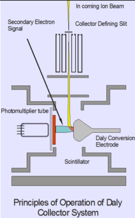
The Daly detector was designed by N.R Daly in the 1960s. The design uses a conversion dynode to convert incident ions into electrons. It also separates the multiplication electronics away from the ion beam preventing secondary ion production on the multiplication dynodes. The conversion surface is a highly polished, aluminised metal surface that is biased at ~25KV. The bias voltage controls the peak shape and to some extent the transmission. However, the efficiency variation is very small above 20KV. Ions impact onto the Daly conversion electrode which releases electrons. These are repelled onto a scintillator forming photons. The photons are detected by a photomultiplier which is external to vacuum. This is radically different to an electron multiplier where the active surface of the multiplier is in the line of sight of the ion beam and the multiplication stages are all in vacuum. The photomultiplier used is a Hamamatsu tube SN R6247, which replaces the earlier Photonis XP2900 tubes. Substantial modifications to the ion counting electronics have been made to ensure the multiplication electronics and discrimination are close coupled to the tube, this has eliminated “ringing” and double counting.
Introduction
Ion counting detectors are used to measure extremely small ion currents typically between 1e-16 and 1e-13 amps. For applications that involve large isotope ratios such as uranium or radiogenic lead, or indeed for zircon geochronology where the Pb contents of individual zircons is extremely variable, it is crucial that ion-counting detectors have a linear response.
Non linearity of ion-counters is due to a combination of factors which have been discussed at length in the literature (e.g. Richter et. al 2001). Potentially the largest source of error is the calibration of the deadtime (DT).
The deadtime is the period after a count has been registered before another ion can be counted and ideally it should be constant irrespective of count rate.
Typically the DT is a few tens of nanoseconds but it must be measured accurately to minimize its affects at high count rates. For example a count rate of 1e6 cps equates to a time between counts of 1 microsecond and a 10ns deadtime would be a 1% contribution.
Richter et. al. have shown that at count rates greater than ~20,000 cps, Secondary Electron Multipliers (SEMs) are non-linear even after DT correction . The non-linearity becomes larger at higher count rates and can be as high as 1% at 6e5 cps.
Ion-Counting Daly Detector
The main axial ion-counting system used on all Isotopx TIMS instruments is an ion-counting Daly detector. The principle of operation is described in the box above.
The Daly detector offers a number of advantages over SEM type ion-counters. It has a large dynamic range, providing several orders of magnitude overlap with the Faraday collectors. It has the highest gain stability relative to the Faraday collectors, and the largest working peak flat. Several Daly systems have been in continuous operation for over twenty years without replacement of any component.
The Daly on Phoenix and Phoenix X62 TIMS represents the next generation of ion-counting detector. Isotopx have re-designed the Daly to take advantage of the latest developments in photo-multipliers and in counting electronics.
Compared to earlier Daly units this new system has lower noise and a larger dynamic range. The issue of ‘ringing’ has been eliminated which, combined with lower noise, allows a significantly more efficient rejection of false counts.
The purpose of this note is to demonstrate the improved performance of this new Daly system.
Method
The isotopic standard NBS U500 was measured by peak jumping 234U, 235U, 236U and 238U on the ion-counting Daly detector. The isotope ratios 234U/238U and 236U/238U are corrected for mass fractionation using 235U/238U.
The certified ratio of 235U/238U is 0.99968 hence 235U and 238U are essentially the same size. Consequently any detector non-linearity will be cancelled out when a ratio is calculated. This means that a fractionation correction applied using 235U/238U will have no effect on any detector non-linearity that might be present on other isotope ratio’s.
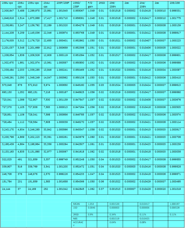
The sample was loaded onto the side filament of a triple filament and the intensity adjusted by controlling the side filament current. Measurements were made at different intensities of 238U over the course of several days. Each analysis took a minimum of 2 hours, and this was increased for the lower count rate measurements in order to obtain the required precision for the minor isotopes. Isotopes were also simultaneously detected on the off – axis Faraday collectors, such that the Faraday/Daly gain could be determined at different count rates. Table 1 shows the analytical sequence.
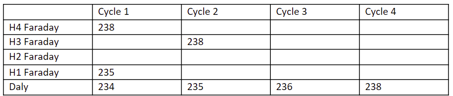
The analysis consists of peak jumping 234, 235, 236 and 238 on the Daly. Integration times are 5 second, 3 second, 5 second and 3 second respectively. In cycle 1, 235U and 238U are measured on the off axis Faradays.
The results are shown in Appendix 1. A deadtime of 39.5ns was used for all the data.
Faraday/Daly Gain
The Faraday/Daly gain was determined by measuring the 235U/238U on the Faraday collectors in the first cycle, and 235Daly/238F in the second cycle. Cycle 1 is divided by cycle 2, to obtain the gain.
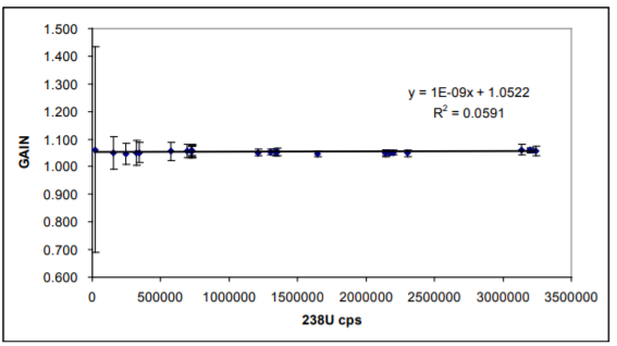
The data shows that relative to the Faraday collector the Daly is 94.8% efficient and this efficiency remains constant from 24,000 cps of 238U to >3e6 cps of 238U (Figure 1).
Figure 1 also gives a good indication of how linear the Daly is. If we assume that the Faraday is linear then there is no change in Daly gain from 24,000 cps of 238U to >3e6 cps of 238U. Determining the linearity at low count rates is difficult because of the noise of the Faraday collectors.
Daly Linearity – 234U/238U
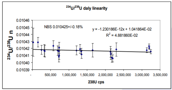
234U/238U data are shown in Appendix 1 and Figure 2. The average of all the determinations is 0.010417+/- 0.11% 2 RSD. The dynamic range covered is 252cps 234U to 3.2e6 cps 238U. The mean ratio compares to the reference value of 0.010425 which has an error of approximately 0.2%. The mean accuracy is 0.08%, so the results are within error of the certified value. A linear regression line through the data produces an intercept of 0.010419. The slope of the regression line is 1e-12, confirming that the Daly is completely linear with one deadtime correction.
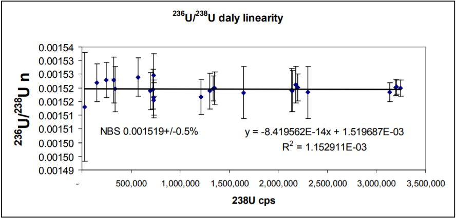
Daly Linearity – 236U/238U
236U/238U are also shown in Appendix 1 and Figure 3. The ratio is more extreme than the 234U/238U. The average of the determinations is 0.001520±0.34% 2RSD. The lowest 236U determined is 37cps. The regression line through the data shows zero slope, and so the Daly is totally linear with the one deadtime correction. The intercept is indistinguishable from the reference value.
Comparison with SEM detectors.
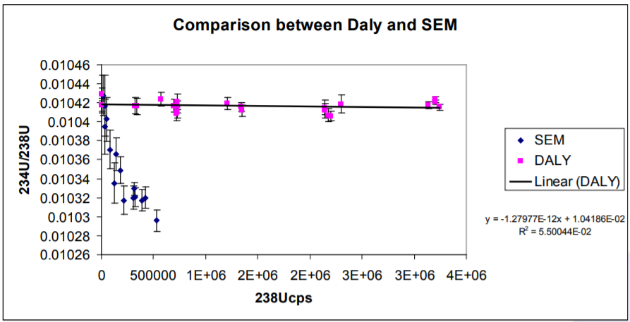
Richter et al 2001, compared a number of SEM detectors commonly used on isotope ratio MS instruments. They showed that a single deadtime correction could not be applied to SEM detectors and an empirical ‘best fit’ curve must first be determined and then applied to acquired data. This became more important for counting rates above 20,000cps as above this level the non-linearity of the SEM’s under test became significant.
The results for 234U/238U presented here are compared with those of Richter et. al 2001 in Figure 4. The difference in behaviour between the Daly and an SEM is very clear and highlights the significant benefits of the Daly system over the SEM’s tested by Richer et al.
Reference
S. Richter. Goldberg,S.A, Mason, P.B., Traina, A.J. Schweiters, J.B. 2001. Linearity tests for secondary electron multipliers used in isotope ratio mass spectrometry. International. Journal of Mass Spectrometry. 206. 105-127.
Download Technical Note
Download the complete Technical Note: An assessment of the linearity of the ion-counting Daly detector