Application note AN22_01
Matt Hockley, Isotopx Ltd, Dalton House, Dalton Way, Middlewich, Cheshire, CW10 0HU, UK.
How do I select an integration time to optimise my measurement precision?
Introduction
When measuring an ion beam, there are two sources of uncertainty on the measurement: uncertainty due to amplifier noise, and uncertainty due to the shot noise of the beam. Shot noise improves with integration time t in proportion to √t, as does the noise of a traditional resistor amplifier. However, the noise performance of the Isotopx ATONA amplifier improves in proportion to the integration time t.
The effect of integration time
The effect of integration time on measurement precision can be investigated by considering the ratio of shot noise to amplifier noise at a given integration time. For a resistor amplifier, since both of these quantities scale with √t, for a given beam intensity the ratio is constant, and the integration time makes no difference. With the ATONA, this ratio increases with increasing t due to the different rates of improvement with t. This is to say, the contribution of the amplifier noise to total uncertainty in a measurement decreases with increasing integration time when using the ATONA amplifier, while it is constant with a traditional resistor amplifier. This is a distinct advantage for ATONA versus traditional amplifiers, as the latter offers diminishing returns for extending integration time, whereas longer integration times for ATONA continue to improve noise levels in direct proportion.
This suggests that longer integrations should always be preferred when using the ATONA amplifier. However, this reduces the total number of integrations obtained. An optimization may then be made where the integration time is such that the contribution of amplifier noise to total uncertainty is negligible, and the total number of integrations is maximized. This optimization results in an integration time dependent minimum beam intensity for the ATONA, in contrast to the fixed minimum beam intensity for a resistor amplifier (approx. 50 – 100 mV for a 1E11 ohm amplifier) before data begins to degrade.
A further factor for consideration is that long integration times are needed by conventional amplifiers, in part because of long Tau decay times, especially with the largest resistors. The ATONA system reduces this factor due to significantly reduced Tau decay times, meaning ATONA can be used with a wider range of integration times.
Integration time optimisation
To provide instrument operators with some guidance as to appropriate integration times for a range of beam intensities, a graphical representation of this optimization for the ATONA system as used on Phoenix TIMS is presented in Figure 1.
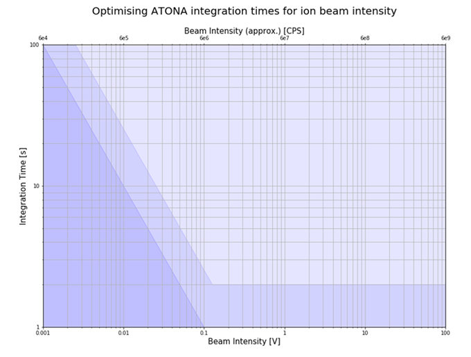
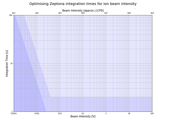
The optimal integration times are denoted by the mid-blue region. The dark blue shading in Figure 1 denotes the region in which amplifier noise is a significant contributor to total measurement uncertainty, so a longer integration time may be preferred to prevent degradation of data. The light blue shading denotes the region where the benefit to longer integration times is negligible, so a greater number of shorter integrations may be preferred. A similar representation of the optimization for the Zeptona detector system is presented in Figure 2.
It should be noted that this is intendent to provide a reasonable starting point, but other factors may influence the integration time used. For example, in a peak jumping analysis with beams of 1 V, a longer integration time may still be preferred due to the duty cycle advantage it brings.
Matt Hockley, Zenon Palacz
Download Technical Note
Download the complete Technical Note: