Technical Note 2101
Matt Hockley, Zenon Palacz, Shaun Yardley and Tony Jones, Isotopx Ltd, Middlewich, Cheshire, UK.
Introduction
When measuring very small ion signals (<10,000cps), in sub picogram samples of actinides, ion counting detectors are necessary due to their low noise compared to that of a Faraday detector. Ion counters however, still have a nonzero noise associated with them, known as the dark noise, which is typically several counts per minute (CPM). Additionally, there are sources of measurement error present that are not of concern with Faraday detectors, such as deadtime/linearity, peak flatness, and gain stability. The challenge in determining the relative gain of an ion counter, presents a significant challenge in acquiring high quality data at low count rates.
In this application brief, the performance characteristics of an Isotopx Phoenix equipped with 10 channels of upgraded Isotopx Ion Counting (IIC) power supply and counting electronics is evaluated. The ion counters are conversion dynode multipliers, whereby the ion beam strikes a conversion dynode, and the released electrons are detected using a Sjuts multiplier aligned at 90o relative to the ion beam.
This design allows the simultaneous measurement of actinides at unit mass spacing with no intermediate attached Faraday collectors. In addition the multipliers are independently movable relative to each other, so the same collector array can measure for example U and Pu isotopes as well as Nd, Pb or Os isotopes by adjusting the separation of the ion counters relative to each other.
This instrument is also equipped with a Zeptona Faraday detector which is an enhanced (lower noise) version of the ultra low noise ATONA® amplifier. The Zeptona allows calibration of multiplier gain relative to a Faraday collector at count rates of <~10,000cps which is an ion signal too low for most resistor-based Faraday collectors.
Peak Flatness
Peak flatness can present a significant source of error in ion counting measurement. A significant slope on the flat could result in an apparent gain change depending on where on the peak flat a measurement is made. Using a relatively large conversion dynode will minimize any ion focusing deviations which could give rise to changes in the peak flat. An example of the peak flat is shown in Figure 1, where the peak is flat to better than 0.1% over +/-100ppm of mass.
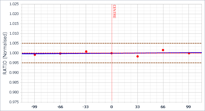
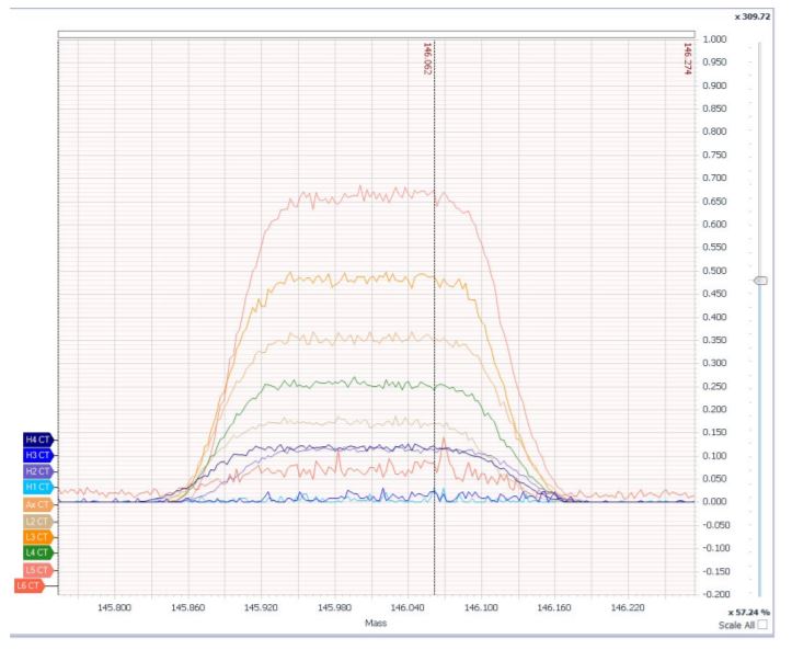
Figure 2 shows a scan over coincident Nd and interference beams on all 10 of the fitted ion counters. This demonstrates the excellent peak shape, peak flat and coincidence achievable with the ion counters over a wide dispersion across the instrument focal plane. This is the first time that an ion counter array has been able to achieve this.
Dark Noise
Dark noise is a measure of the counts registered on an ion counter when no beam is present, and is a critical factor determining the quality of ion counting data at very low count rates. There are two major sources of dark counts – counts due to incident cosmic rays, and counts originating in the ion counting electronics. Counts due to incident cosmic rays are a function of the ion counter size, and cannot otherwise be reduced, while counts due to electronic noise can in principle be eliminated. Ten channels of dark noise data were collected over several hours, with the results shown in Table 1.
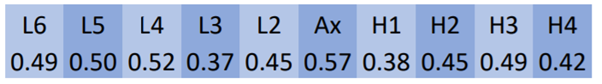
The average of all channels is less than 0.5 CPM, with no channel exceeding 0.6 CPM (0.01 CPS), demonstrating both the extremely low noise, as well as the excellent consistency between channels. This noise level is comparable to the fundamental noise limit expected due to cosmic ray induced counts. This data suggests that a beam of 0.05 CPS (5 x 0.01 CPS) could be reliably resolved from the baseline.
Linearity
All ion counting detectors are inherently nonlinear, i.e. the ratio of detected beam/incident beam varies with beam intensity. The degree of variation can be measured and mathematically corrected by applying a “deadtime” to each ion counting detector. The stability of this deadtime, and how well the mathematical correction describes the actual behaviour of the ion counter is critical, particularly with large ion signals and abundance ratios. Any non-linearity will be observed as a variation of the measured isotope ratio with incident beam intensity.
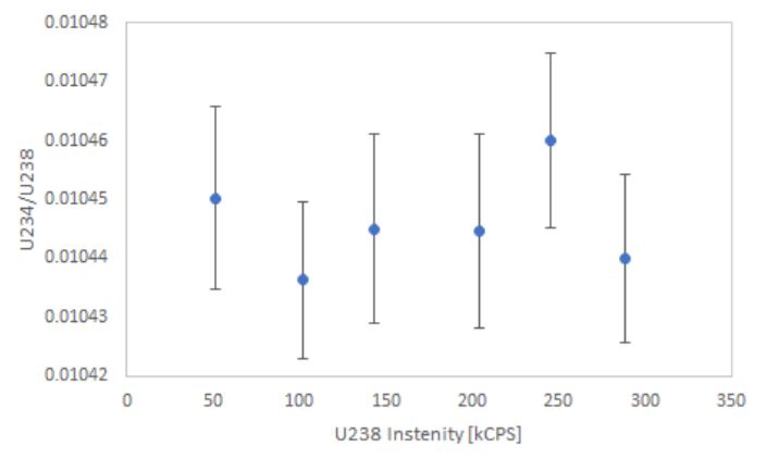
The linearity of the each of the ten ion counters was determined by analysing the 234U/238U (0.01042) ratio of a uranium standard (NBSU500), where the 238U abundance is approximately 100 times greater than the 234U. The analysis was performed with a 238U intensity of 5e4 CPS to 3e5 CPS. Figure 3 shows typical data for the ratio obtained as a function of incident beam intensity. A deadtime of 20 ns was applied to this ion counter. At each intensity the same ratio is produced within experimental error, demonstrating linearity to better than 0.1% 1RSD over the range 5e2 to 3e5 CPS.
Stability
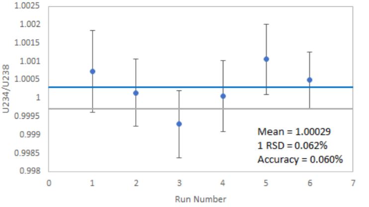
Gain stability of ion counting detectors is critical to consistently producing precise and accurate data. The 235U/238U of U500 was measured on two ion counters over 6 replicate analyses, each of 200 seconds, at 5e4cps 238U.
The results are shown in Figure 4, with the mean of the measured data (blue line) and the certificate value of the standard (grey line) indicated. Note that no mass fractionation correction has been made. There is no apparent gain drift over the measured period, with external reproducibility of 0.06%1RSD, consistent with counting statistics, confirming negligible gain drift between two ion counters.
The stability of the ion counters relative to a Zeptona Faraday was measured over 60 minutes. A 1.6e4 cps ion beam was measured for 2 s in each of the ion counters, and 10 s on the Faraday. A precision of ~0.4% 1 RSD was achieved for each of the 10 ion counters. Data from one channel is shown in Figure. 5, demonstrating the excellent stability over the 60 minutes of measurement, with no evidence of ion counter gain drift.
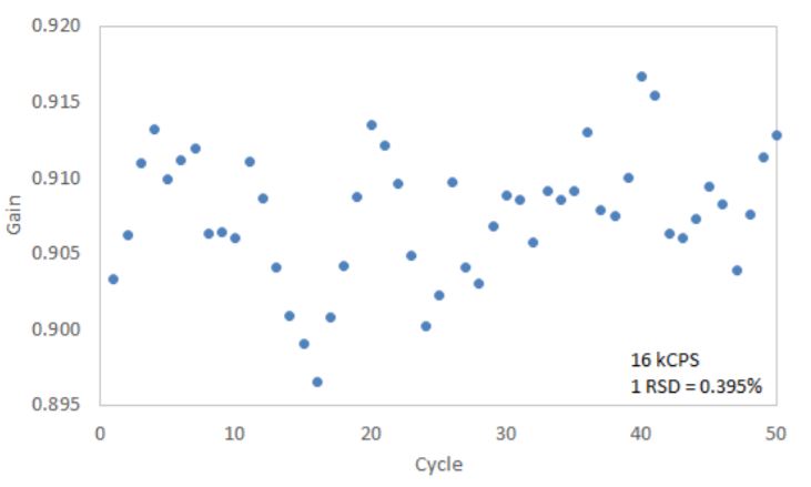
The absolute value of the gain of the channel shown is 90.8%, with the average of all 10 channels being 87.0%. This value is ~5% higher than previously achievable with this design of ion counter. This is due to the very low electronic noise of the system, which allows the discriminator threshold to be set to ~5 mV across all channels, minimising loss of small pulses and therefore increasing gain.
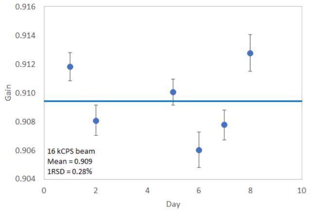
Longer term gain stability was investigated by repeating the above method several times over a period of 8 days. Across all channels the gains were stable to an average of 0.33% 1RSD over the 8 day period, with a typical profile shown in Figure 6.
Zeptona Faraday
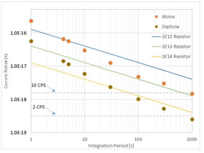
The Isotopx Zeptona Faraday detector employs a single channel ATONA® amplifier and custom rear Faraday detector, both optimised to minimise noise, while retaining all the advantages of the ATONA® amplifier. Figure 7 shows the noise characteristics of the Zeptona amplifier over a wide range of integration times, with ATONA® amplifier data and theoretical resistor amplifier performance shown for reference. The Zeptona achieves noise levels around 5 times lower than those of the ATONA® at all integration times. The noise of the Zeptona amplifier is comparable to the theoretical noise of a 1e14 ohm resistor at integration times greater than 10 seconds.
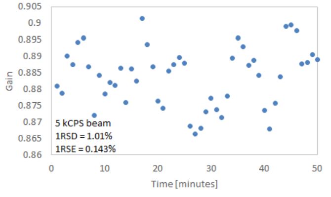
To demonstrate the use of the Zeptona Faraday to calibrate ion counter gain with very small ion signals, a 5e3 CPS 238U beam was measured on all ion counters (2s integrations) and the Zeptona Faraday (10s integrations). Figure 8 shows the results from a typical channel, with a precision of better than 0.15% (1RSE) achieved after 1 hour (50 cycles). All 10 channels were simultaneously calibrated to this precision during this analysis. This precision is consistent with ion counting statistics, demonstrating that even at very low beam intensities the Faraday noise does not limit gain calibration precision.
The Faraday’s maximum signal of 1e-8A (~6e10 CPS, 1000V), in conjunction with the low noise of the ion counters, provides a detection system with 12 orders of magnitude dynamic range.
Conclusions
The Isotopx Ion Counting system offers excellent versatility and performance in applications requiring the lowest possible noise and largest dynamic range:
- Configurable with up to 10 movable ion counters and one fixed Zeptona Faraday. A Daly detector and WARP abundance sensitivity filter may be fitted in addition to the Faraday.
- Ion counting noise of 0.5 CPM, and single channel Faraday noise of ~ 40 CPS at 10 s integrations – comparable to 1e14 Ohm resistor amplifier.
- Excellent peak shape and flat over the focal plane – makes static and multidynamic ion counting analysis possible to eliminate gain effects.
- Stable to < 0.4% RSD over 1 hour.
- Stability over several days’ comparable to short term stability.
- Linear to < 0.3% RSD up to 3e5 CPS.
- Zeptona Faraday allows robust ion counter gain calibration with beams as small as a few kCPS.
- Detection of beams from 0.05 CPS (0.8 nV) to >6e10 CPS (1000 V), providing 12 orders of magnitude dynamic range.
Download Technical Note
Download the complete Technical Note: Ultra Low Noise Multiple Isotopx Ion Counting (IIC) and Faraday Detectors on Phoenix TIMS